
“How good is good enough?” At some point, component “goodness” will drive cost. Sometimes, “very good” is not really good enough, and sometimes it is overkill that doesn’t warrant the cost. For critical and cost sensitive assemblies, it’s imperative to perform a rigorous design analysis that will determine the requirements of the assembly components and procedure, including the Torque-Tension Repeatability requirement. The recommended design methodology and analysis is defined in “VDI 2230 Systematic calculation of high duty bolted joints with one cylindrical bolt”. One result of this method is the bolt tension requirement. This, and the strength of the bolt, define the lower and upper limits for bolt tension. In addition, the calculation provides insight to the conditions that contribute to the tension requirement (bolt length, loading, embedding, stiffness of the clamped members, etc., etc.). Very often there are configuration or method changes that can improve the success of the assembly while lowering the cost of components. In general, there is a cost trade-off between the accuracy of final tension, and the size/strength/number of fasteners to generate that tension. The challenge is to find the component configuration and assembly method that satisfies performance with the lowest total cost.
The goal of the assembly process is to achieve the target tension in the bolt. If torque is used to generate the tension, torque is the independent variable (input), and tension is the dependent variable (output). The torque-tension relationship is very often described with
T = KFd (1)
where T is the final assembly torque, K is the dimensionless assembly coefficient, F is the final assembly tension, and d is the nominal diameter of the bolt and nut. There are three problems with using this equation to describe assemblies with prevailing torque locknuts:
1. It suggests that torque is the dependent variable and tension is the independent variable. The equation would be better stated as
F= T/(Kd) (2)
2. It suggests that the torque-tension relationship is described by a straight line through the origin, with a slope of 1/(Kd). A better equation, that accounts for prevailing torque, is
F= (T – t)/(Kd) (3)
where t is the prevailing torque (T = t while tension is zero). Equation 3 more accurately describes the affect prevailing torque has on the torque-tension relationship; prevailing torque consumes some of the drive torque.
3. It doesn’t describe the contribution to the torque-tension relationship of thread pitch (coarse vs. fine), bearing surface diameter (flange locknut/bolt vs. hex locknut/bolt), or the difference between bearing surface coefficient of friction and thread interface coefficient of friction. There is an almost universal misunderstanding that the K value that was determined for a coarse hexagon locknut that bears on a painted surface can accurately be applied for a fine thread flange locknut that bears on an unfinished surface. A more descriptive torque-tension relationship equation is
T – t = F[P/(2π) + 0.577 d2 µt + μn De/2] (4)
where P is the axial distance per thread, d2 is the basic pitch diameter, µt is the coefficient of friction at the thread interface, µn is the coefficient of friction at the bearing interface, and De is the effective bearing diameter of the driven component (bolt or locknut). Comparing equations 3 and 4 reveals
K = [P/(2π) + 0.577 d2 µt + μn De/2]/d (5)
Using equation 5, one can evaluate the error that would result from applying the same K to various configurations.
So, if K changes from one configuration to another, why use it to describe the torque-tension relationship? Using K may serve for “rule of thumb” between configurations that are fairly similar, but for applications where assembly and in-service performance are critical, it might be best not to use K; using K might just obscure a better understanding of the actual torque-tension relationship.
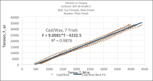
To be clear, the requirement of torque-tension repeatability should be stated with respect to variation in final tension, as this relates directly to the bolt tension accuracy requirement. If we describe the torque-tension relationship with
F = m(T – t) (5)
Where m is the slope of the best-fit line for actual torque-tension data, and t is the Torque-axis intercept of that line, we can develop the sensitivities to final tension variation from variation of the inputs, m, T, and t.
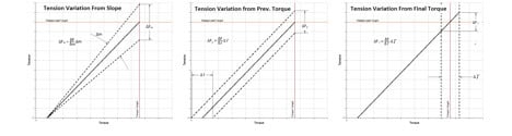
Taking partial derivatives of equation 5 yields
δF/δm = (T - t) (6)
δF/δt = -m (7)
δF/δT = m (8)
For a given configuration, variation in m is mostly attributable to variation in coefficient of friction. In many cases, reducing the variation in m is accomplished with lubrication or fastener coatings with lower coefficient of friction. The assembly designer should be aware that lower coefficient of friction will increase m, and so amplify the sensitivity to variation in final torque (usually drive method accuracy) and the sensitivity to variation in prevailing torque.
To summarize:
1. Find the allowable tension variation using the VDI 2230 method and the size/strength/number of the fasteners that create that tension.
2. Determine the lowest cost combination of
a. Low variation in coefficient of friction (plating/coating, that also might have to provide corrosion protection)
b. Low variation in prevailing torque
c. Low final variation in assembly torque (defined by the assembly drive tool)
Other things to consider:
1. Lower coefficient of friction and smaller variation in final tension might allow for smaller fasteners and a smaller assembly drive tool, which possibly would increase the budget for the better drive precision necessary to achieve the smaller variation in final tension.
2. Lower coefficient of friction has been shown to adversely affect the self-loosening mechanism during transvers motion (Junkers) vibration tests (“Effect of Thread and Bearing Friction Coefficients on the Vibration-Induced Loosening of Threaded Fasteners”, Housari and Nassar, Transactions of the ASME, Vol. 129 August 2007).
3. If one source of variation is significantly larger than the others, reducing the other variations will have very little effect. Specifically, if the accuracy of final assembly torque is very bad, improving the variation in the coefficient of friction or prevailing torque may be a waste of time and money.
