
In the vast majority of threaded fastener applications, there are valid reasons for opting for nuts or locknuts with flanges instead of using the “un-flanged” nut with a washer. If the application calls for a deflected-thread all-metal locknut, there are additional reasons. This blog entry will identify those reasons and provide supporting arguments.
The German Society of Engineers has published a standard VDI 2230 – Systematic calculation of high duty bolted joints with one cylindrical bolt. The guidance and calculations presented therein will be applied to quantify the comparison of flanged and un-flanged (with washer) nuts, where that standard covers such calculations.
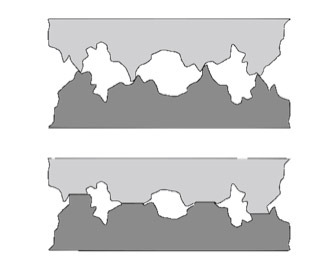
Embedding and Relaxation
Every surface, when examined microscopically, has high and low points according to the surface roughness. These high points are sometimes referred to as asperities. When two surfaces are in contact, the asperities of each rest on the asperities of the other. Embedding is the process where, when two surfaces are loaded against each other, the load transferred through the asperities locally exceeds the yield stress of the material, and the asperities yield, or “wear”.
VDI 2230 dedicates paragraph 5.4.2.1 to the loss of preload due to embedding and relaxation. Table 5.4/1 addresses embedding, quantifying the effect.
VDI 2230 Table 5.4/1. Guide values for amounts of embedding of bolts,
nuts and compact clamped parts made of steel
| Average roughness height Rz according to DIN 4768 | Loading | Guide values for amounts of embedding in μm |
||
| in the thread | per head or nut bearing area | per inner interface | ||
| < 10 μm | tension/compression shear |
3 3 |
2.5 3 |
1.5 2 |
| 10 μm up to < 40 μm | tension/compression shear |
3 3 |
3 4.5 |
2 2.5 |
| 40 μm up to < 160 μm | tension/compression shear |
3 3 |
4 6.5 |
3 3.5 |
Relaxation is loss of preload due to material creep under load, and is a function of stress, time, and temperature for a given material. Using a hex nut and washer instead of a flange nut introduces an additional inner interface, and the associated additional preload loss due to embedding and relaxation in that interface. For instance, ISO 10683 briefly recognizes, but doesn’t quantify, the relaxation of non-electrolytically applied zinc flake coatings on the bearing surfaces of steel fasteners, because those coatings include a polymer resin matrix that can relax under typical load and environmental conditions. Preload loss occurs because the clamped length decreases by the amount of embedding and relaxation, will depend on the initial clamped length and the stiffness of the clamped members and the bolt, and must be accounted for during assembly. The preload loss happens after assembly, when the joint “starts to be used”, and so won’t be eliminated during assembly. Significant preload loss erodes the tension budget (the difference between the maximum tension that doesn’t break the bolt and the minimum tension that allows the assembly to stay assembled, minus design margins).
Loosening Torque
Paragraph 5.4.3 of VDI 2230 discusses assembly preload and tightening torque, and develops equation 5.4/20, restated below, for threads with a 60° flank angle.
MA = FM[0.16 ⋅ P + 0.58 ⋅ d2 ⋅ µG + (DKm ⋅ µK)/2]
In this equation, MA is the total tightening torque, FM is the tension in the bolt, P is the thread pitch (distance per thread), d2 is the basic pitch diameter of the thread, µG is the coefficient of friction in the thread interface, µK is the coefficient of friction in the bearing interface, and DKm is the diameter required for measuring the coefficient of friction acting at the bearing face of the driven component. Since friction forces always oppose the direction of motion, the equation can be modified to
MAl = FM[0.16 ⋅ P - 0.58 ⋅ d2 ⋅ µG - (DKm ⋅ µK)/2]
where MAl is the loosening torque, and the more negative its value, the more a joint will resist loosening. Many references (ISO 16047, DIN 946, etc.) approximate DKm as the mean between the inner and outer diameters of the bearing surface, or
DKm = ½(Db + Dcs)
where Db is the outer bearing diameter and Dcs is the countersink (inner) diameter. I think the more accurate quantity is the diameter that splits the bearing area in half, which can be calculated as
DKa = [½(Db2 + Dcs2)]½
DKa is always larger than DKm , and should be more accurate than DKm if the bearing force is evenly distributed across the bearing area. DKa could still be a conservative approximation if the surface of the flange is concave, causing greater loading at the outer edge of the flange.
Since a flange nut usually has a larger Db than a hex nut, it will also have a larger DKm or DKa , it will require more torque to create a given tension force, and it will also resist loosening to a greater extent, which is desirable. For example, a ½” flange nut with a bearing diameter of 1.00” and a countersink diameter of 0.53” has a DKa that is 25% or more larger, and a DKm that is 20% or more larger, than the 1/2” hex nut with a bearing diameter of 0.74” and the same countersink diameter. In this case, the flange nut has 25% or more bearing friction torque than the hex nut. Having a flange or not does not affect the friction torque in the thread interface.
Parts Count
Using a washer increases the parts count, requiring a 50% additional supply and inventory overhead and assembly complexity per joint. Usually, the overhead and complexity can be directly converted to additional joint costs which outweigh any marginal direct cost difference between the flange nut and the hex nut plus washer.
Assembly Start
For all-metal deflected thread prevailing torque locknuts, the localization of the thread deflection is dependent on the nut material hardness, location and direction of the deflecting impact, and overall nut geometry. For example, if the material is softer, and the cross section of the area being deflected is thinner, and the deflection is axial (i.e., top lock) the deflection can be highly localized. Conversely, for hard, thick-walled nuts deflected radially (i.e. side lock), the thread deflection will be distributed across more of the threads in the nut. When the deflection includes the first (start) thread, it may impact the ease of starting the assembly.
Flange nuts have the advantage of the flange material supporting and preserving the start thread. Hardened flange nuts can withstand significant radial deflection and still start the assembly easily, where a hex nut would not.
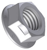
Radial deflection of hardened flange nuts, similar to the figure above, represents the greatest opportunity to control prevailing torque while still preserving ease of assembly start, compared to all other thread deflection techniques and configurations. Without the flange to support the first thread, the performance or cost would be compromised, for
- Torque variation and cost due to the hardening process repeatability and cost, if the parts are deflected prior to hardening
- Torque variation due to the variation in co-location of the deflection and the thread exit from the top of the nut
- Torque performance margin reduction to maintain thread start (trading removal torque for thread start)
- Cost of initial tap-oversize or secondary re-tap operation to allow thread start
In Defense of the Hex Nut and Washer
I have seen arguments in defense of using a hex nut and washer, and offer these rebutting comments:
- When the hex nut Nut Factor (K) is used for a flange nut assembly, the result is 10 to 15 % less tension at the same torque. This is exactly the point of using a flange nut; more loosening (at the expense of more tightening) torque required at the same tension. The assembly will tend to stay together better for the same bolt tension. Simply, don’t use the same K for different configurations (b.t.w., there is a similar, yet smaller effect on K going between coarse and fine thread).
- The Nut Factor (K) is sensitive to the concavity of the flange. This is true, and if the application depends on control of K, flange concavity should be controlled. Controlling concavity is not as difficult or expensive as to outweigh the benefits of the flange.
Summary
Removing an inner interface from the assembly reduces embedding and relaxation losses in preload. And since the flange has a significant effect on the effective “bearing friction” diameter, the nut factor used for defining tightening should recognize the difference, and probably be determined empirically, but results in a higher loosening torque for a given bolt tension. For all-metal prevailing torque locknuts, flange nuts with controlled flange concavity can offer better overall cost and performance and easier assembly when compared to the alternative of hex locknuts and washers.
